
Sending a Device Command With an Argument
This guide assumes familiarity with the following information:
- The basics of the editor (Using Bixby Home Studio)
- The
Commandnode (Sending a Device Command)
In this guide, you'll learn how to send a command with an argument to a device. The device used in this guide is a SmartThings-enabled TV. You'll also be introduced to the Utterance Parameter node.
Take the example "Set the #{Device} volume to 75". The goal is to define the action flow for this voice intent, which will set the volume level of a TV to a user-supplied value.
Utterance Parameter Node
For this voice intent, the user must give Bixby an integer value between 0 and 100:
Example: "Set the #{Device} volume to 75."
This value the user gives gets passed to the Utterance Parameter node. This node stores the value for a specified device parameter. Normally, the node gets the input value from the user utterance, but in Bixby Home Studio you can configure the node with a default value. For testing purposes, you can use this default value, which allows you to test the action flow on a device without an actual user utterance.
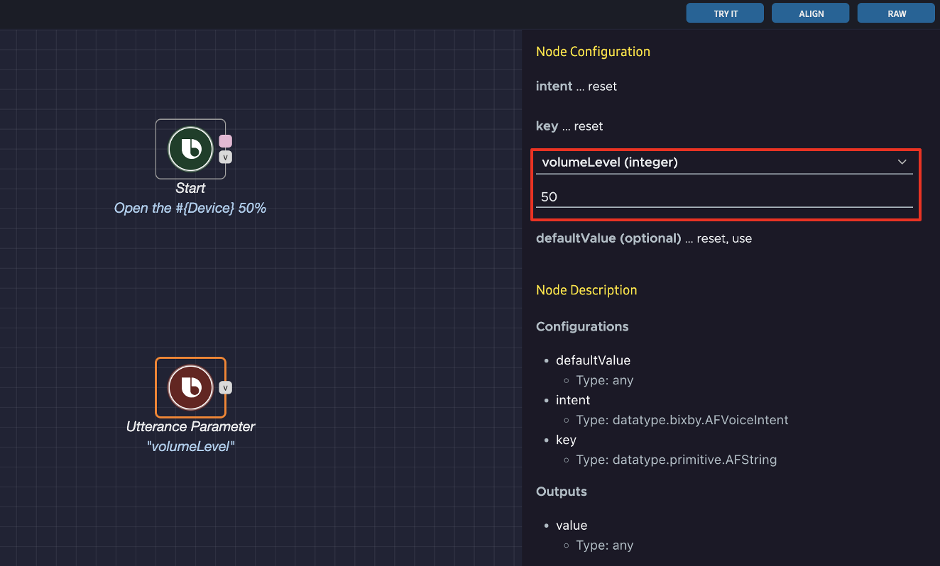
Start building your action flow by dragging the Start and Utterance Parameter nodes from the action flow nodes sidebar to the editor area. Then, configure the Utterance Parameter node:
- Click the
Utterance Parameternode. This opens the Node Configuration menu on the right of the editor area. - In the data type menu, select volumeLevel (integer). This sets the node parameter type to integer.
- Below your data type selection, enter an integer between 0 and 100 in the defaultValue field.
Send a Command
Now, you need to send a command to the device to set the volume level of the TV to the user's uttered value.
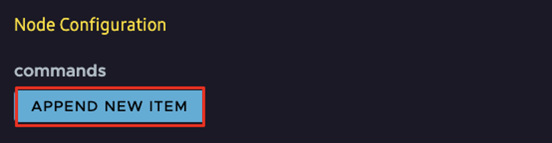
Drag a Command node to the flow editor area. Then, click the node to open the Node Configuration menu on the right. Click APPEND NEW ITEM.
Select main in the component menu. Then, select the audioVolume command in the capability menu.
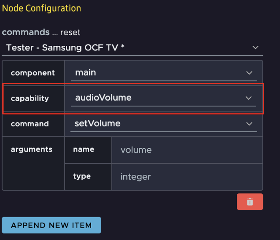
Most devices have only one operating section or compartment. In this case, the only option for component is main. If a device has many sections or compartments that you can operate independently, there will be multiple component options, such as top, bottom, and middle.
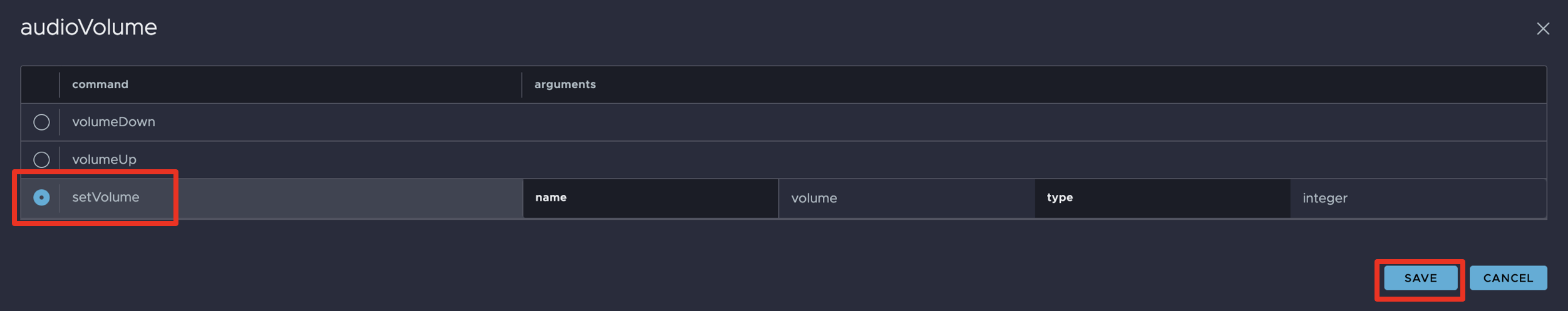
A pop-up for audioVolume opens. Select the setVolume command, which will add input ports for volume level to the Command node. Then, click SAVE.
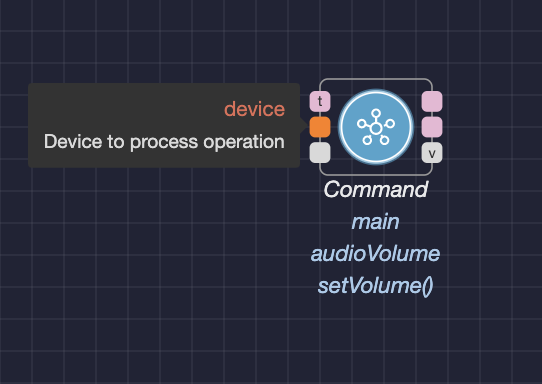
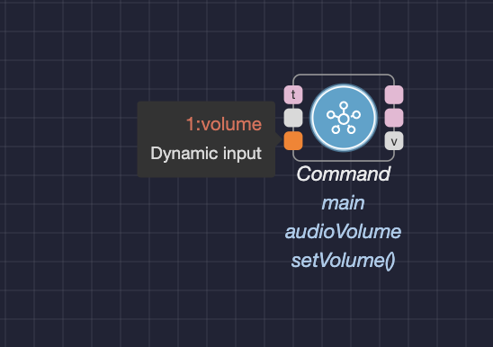
The Command node should now have input ports for device and 1:volume. Since device is an optional argument, you can ignore it for now to keep things simple. The 1:volume input determines the volume level value for this device. The prefix 1: in front of the volume is the sequence number of each command added in the configuration screen of the Command node.
The 1:volume input port is an example of a dynamic input port. Dynamic input ports can be added to a node and their labels can change based on a node's capability. In this case, the number of dynamic input ports and their labels depend on the capability of the Command node.
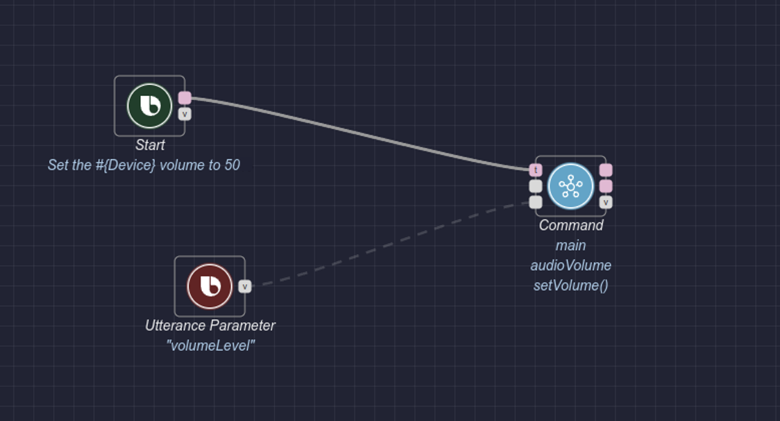
Now you need to connect the Utterance Parameter node's value data port to the Command node's 1:volume data port. You also need to connect the Start node to the Command node's input trigger port.
Here's the finished action path:
Test Your Action Flow
To test the action flow, click the Try It button at the top right of the editor window. The flow editor should look like this:
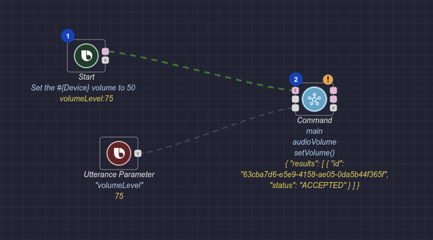
The value of the Utterance Parameter node has been set to 75, and this is used as the mock utterance value. That value is then used to set the volume value for the voice command "Set the #{Device} volume to 75".
You will also see a warning icon  on the
 Command node. When you hover over it, a message states that a response was not generated. This is because there is no Response node in the action flow.
Additional Resources
This guide creates a simple action flow, but you can create action flows of your own with the various nodes and capabilities available to the device you are using.
You can also make more complex graphs by using subgraphs.
For an additional example, see the "Set the Volume of the Device to a Value" Sample Graph.