
Creating a Bixby Response Using Device Status
This guide assumes familiarity with the following information:
- The basics of the editor (Using Bixby Home Studio)
- The
Commandnode (Sending a Device Command)
In this guide, you'll learn how to fetch a device's power status, have Bixby respond to the user, and localize Bixby dialog. The device used in this guide is a simulated light bulb. You'll also learn how to use the following:
AttributenodeResponsenodeVocab Conversionnode for localizationConstantnode
The example "What is the power status of the bulb?" will be used to design an action flow for this voice command.
You must get the status of the device (whether it's turned on or off) and give the user this information. The powerSwitch - getStatus voice intent enables you to do that.
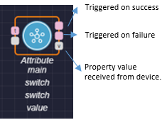
Attribute Node
For this voice intent, you need to fetch the device's power status. Whether the device is powered on is an attribute of the switch capability. To get the value of this attribute from the device, use an Attribute node.
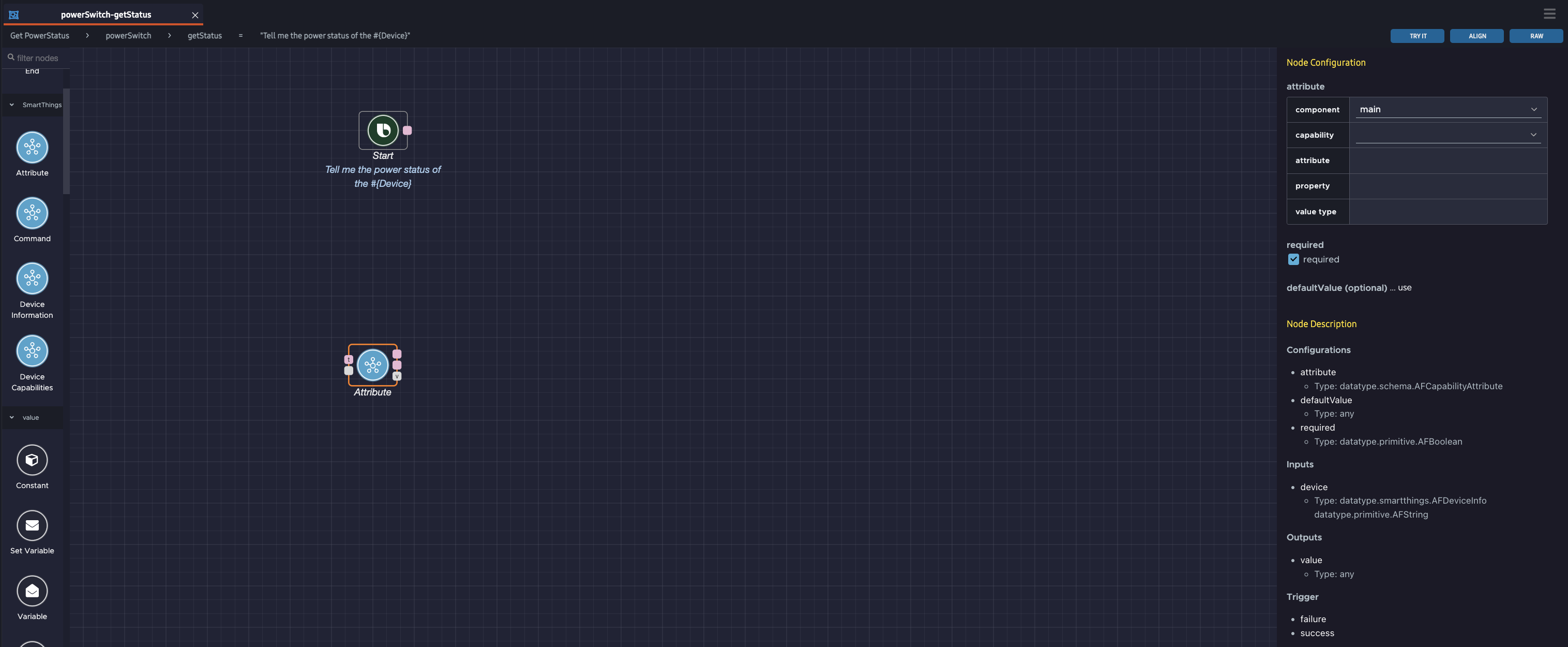
To add and configure this node:
Drag the
Attributenode from the action flow nodes sidebar to the editor area.Select the node. This opens the Node Configuration menu on the right of the editor area.
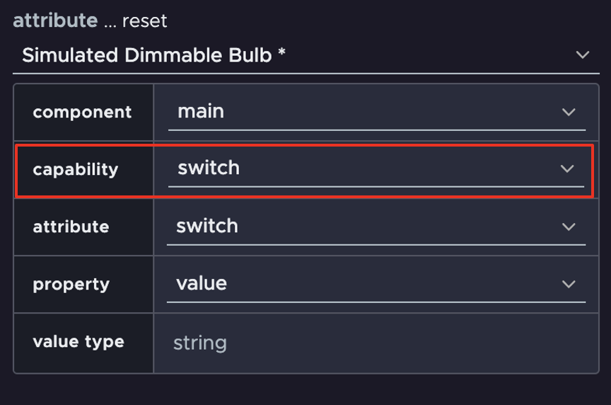
Select the switch capability. In most cases, you can leave the component selection as the default option, main. For more information on components, see the note at the bottom of this section.
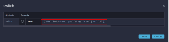
In the pop-up, select the value property for the switch attribute.
Click SAVE.
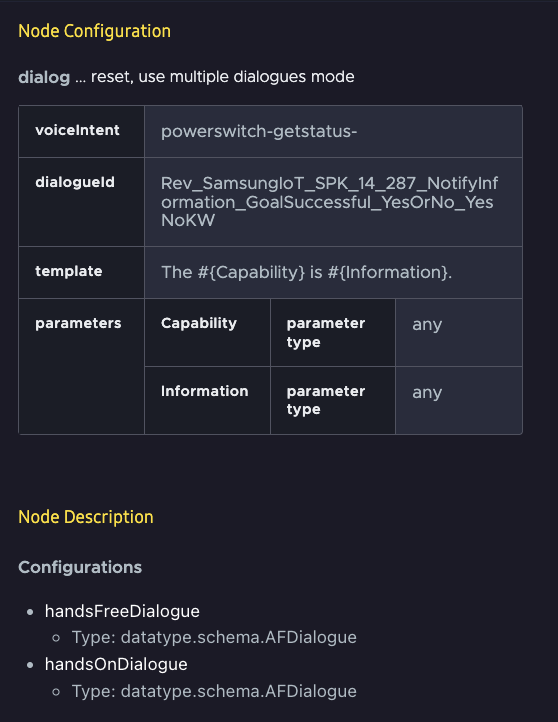
The Node Configuration window will look like this:
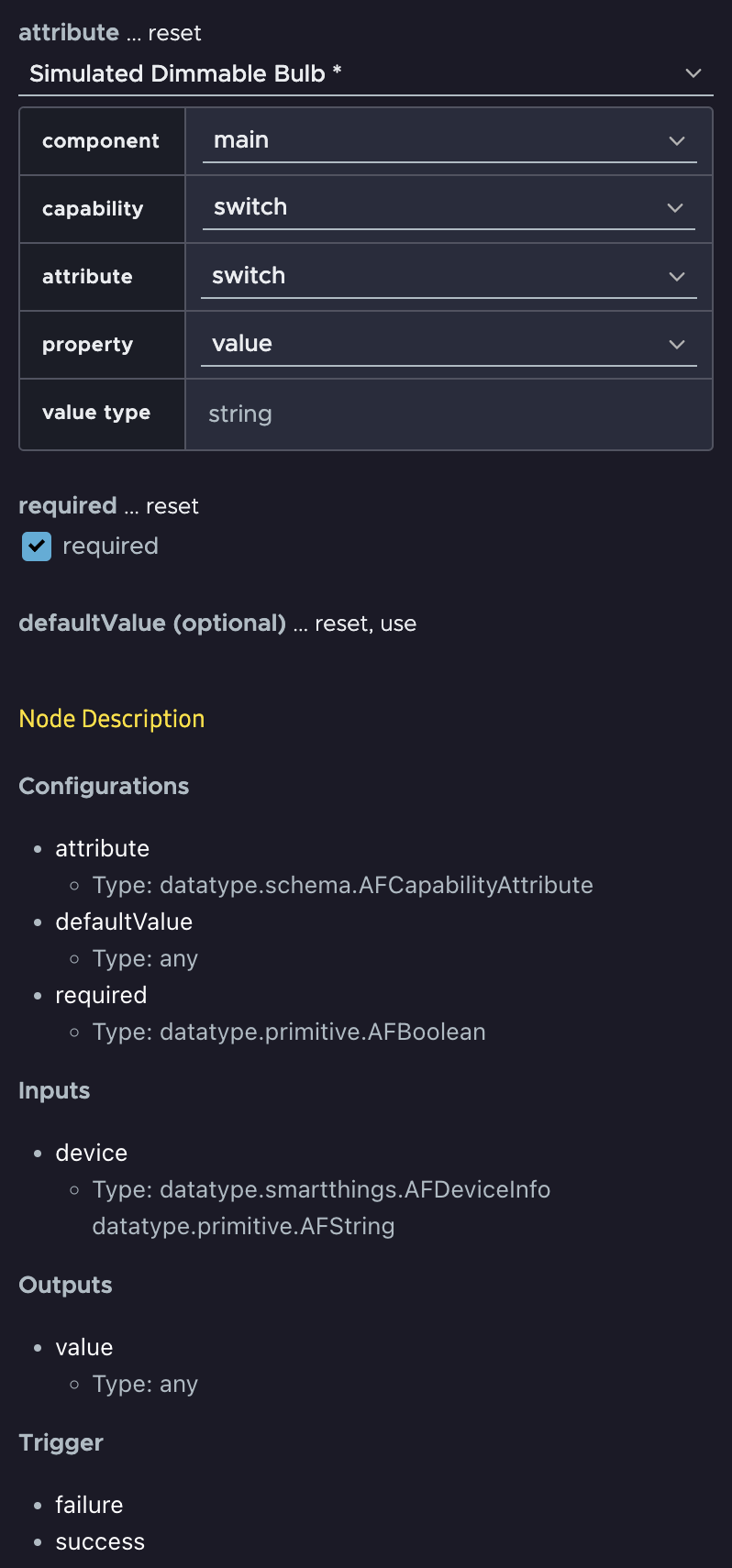
Most devices have only one operating section or compartment. In this case, the only option for component is main. If a device has many sections or compartments that you can operate independently, there will be multiple component options, such as top, bottom, and middle.
Response Node
Now you have the value of the device's power status, "on" or "off", from the output data port of the Attribute node. The value type is string, as seen in the Node Configuration menu earlier.
To have Bixby tell the user the device's power status, use a Response node. The response consists of dialog spoken by Bixby. Drag the Response node from the action flow nodes sidebar to the editor area. Then, select the Response node.
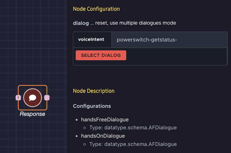
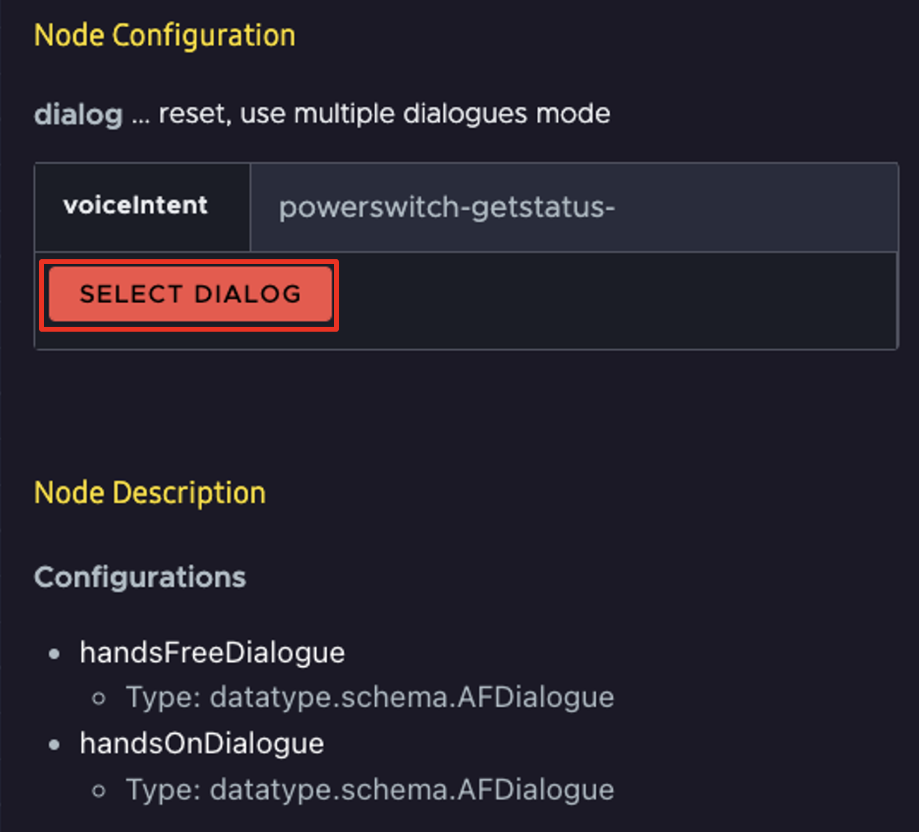
The Response node must be configured for both hands-free and hands-on scenarios. These scenarios are chosen based on the device Bixby is speaking from. You can create different dialogs for each scenario by clicking use multiple dialogues mode under Node Configuration at the top.
In this case, use a single dialog for both scenarios by clicking SELECT DIALOG.
A pop-up with possible dialogs appears. Each dialog response consists of a template and the values to fill in. If you don't find your desired dialog template on the first page, check the bottom right to see if there are additional pages.
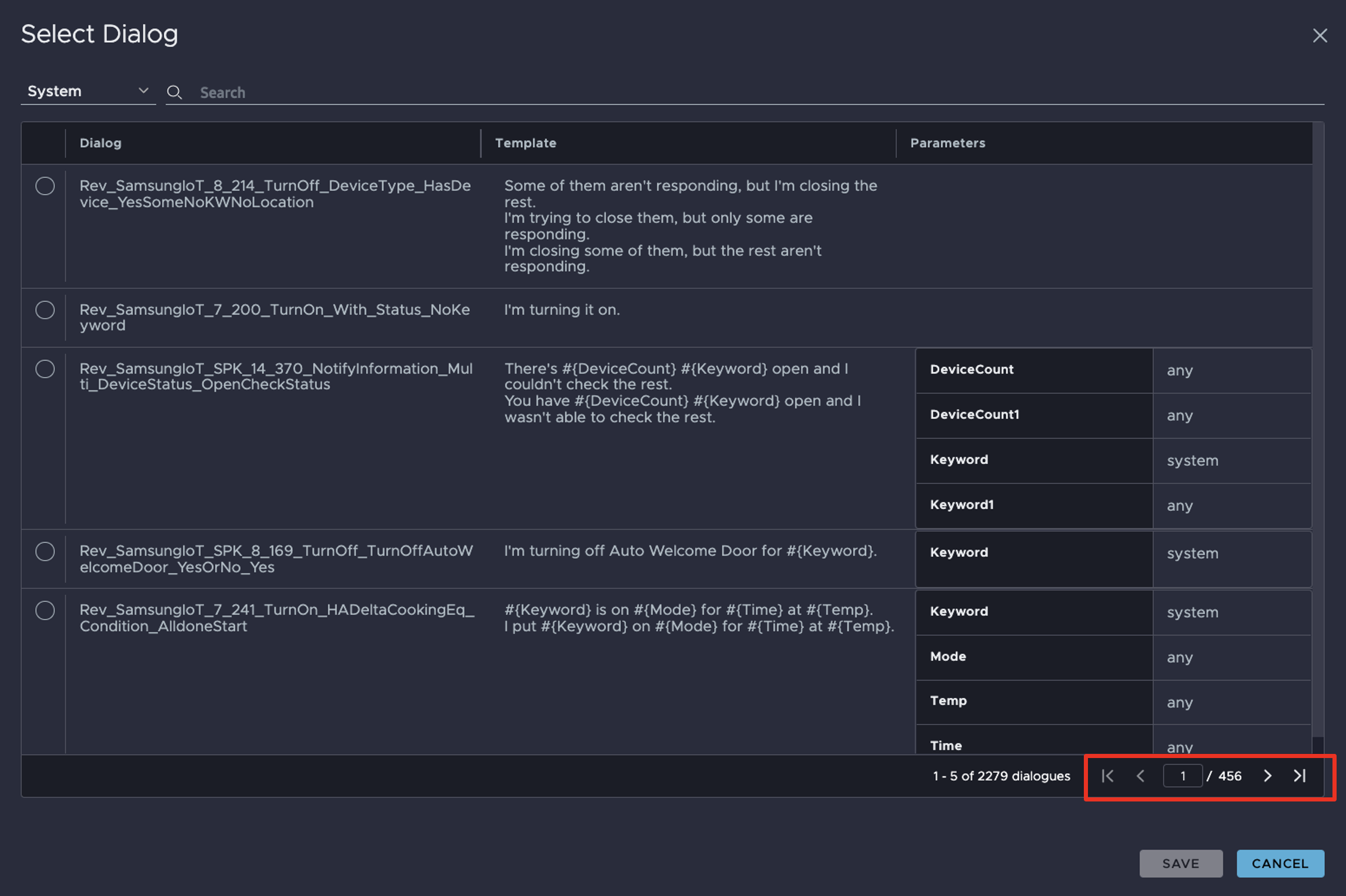
Select the dialog that Bixby uses to respond to the user. For this example, select The #{Capability} is #{Information} and click SAVE.
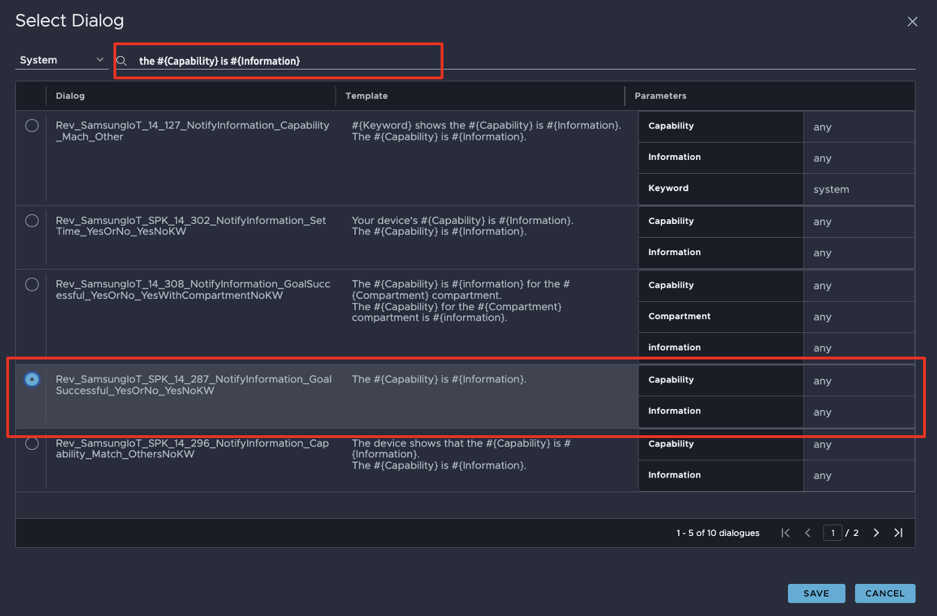
Once the node is configured, the node's ports reflect the necessary parameters according to the chosen dialog. The Information and Capability parameters have input ports on the Response node to receive values via data paths.
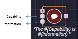
The Capability parameter will be set to the constant string value "backlight", and the Information parameter will be set to "on" or "off".
Localize Metadata With the Vocab Conversion Node
You've configured Bixby to respond to users. Now, you need to pass in the "on" or "off" value.
At first, you might consider directly feeding the "on" or "off" string value from the Attribute node to the input port of the Response node. But you want to ensure that the values are presented in the user's language, and that might not be the exact values "on" or "off". To support multiple languages, Bixby Home Platform (BHP) uses vocab, predefined vocabulary.
The dialog's language is automatically chosen at runtime according to the user's settings. The parameters of a dialog are replaced directly in the dialog's template in that language, to create a coherent response to the user.
The Vocab Conversion node converts a string to a vocab by mapping a key to a particular value. When a key is passed to the node as input, it returns the corresponding vocabulary as output through its node value output port. A key type can be number, boolean, or string. In this case, the possible input keys are "on" and "off."
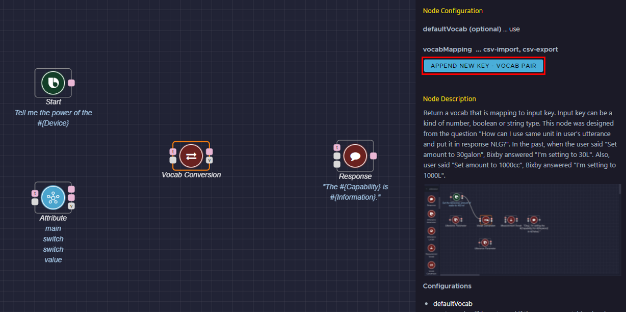
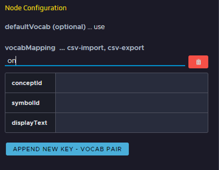
Drag a Vocab Conversion node from the action flow nodes sidebar to the editor area. Select the node. This opens the Node Configuration menu on the right of the editor area. Click APPEND NEW KEY - VOCAB PAIR.
Add a new Key-Vocab Pair for the "on" key by entering "on" under vocabMapping.
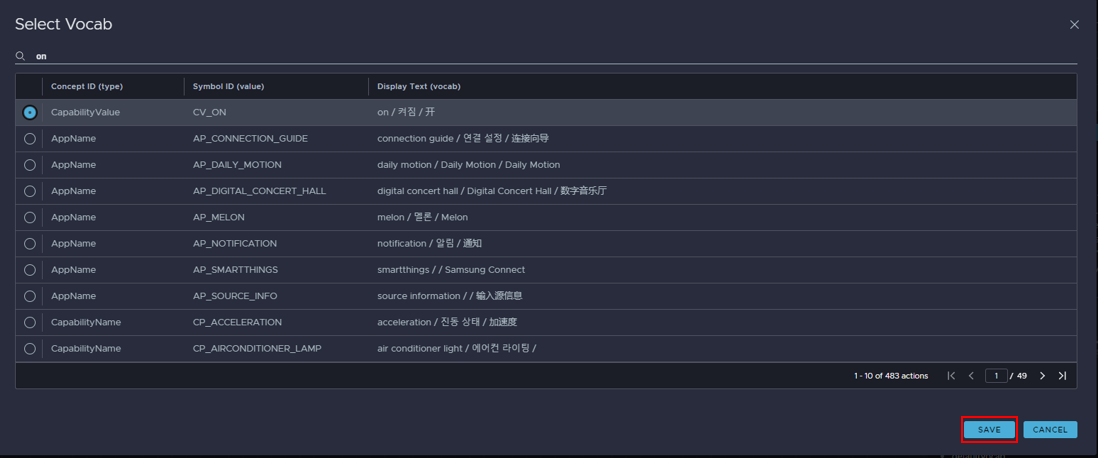
Click on the empty symbolId field. The Select Vocab pop up appears. Select the "on" vocab and click SAVE.
Repeat the steps above for the "off" key.
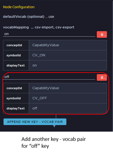
The value of the bulb's power status, "on" or "off", gets input to the Vocab Converter node as a key, and the node outputs the corresponding vocab. The vocab then gets passed to the Response node's Information Input Port as a placeholder for the dialog. This ensures that "on" or "off" is translated appropriately into the user's language and that the dialog is coherent for them.
Constant Node
Now that the Vocab Conversion node is configured, it's time to add a Constant node. This node stores a specified value. In this example, you'll store the string value "backlight", which will be passed to the Capability parameter input port of the Response node.
Drag a Constant node from the action flow nodes sidebar to the editor area. Select the node. This opens the Node Configuration menu on the right of the editor area.
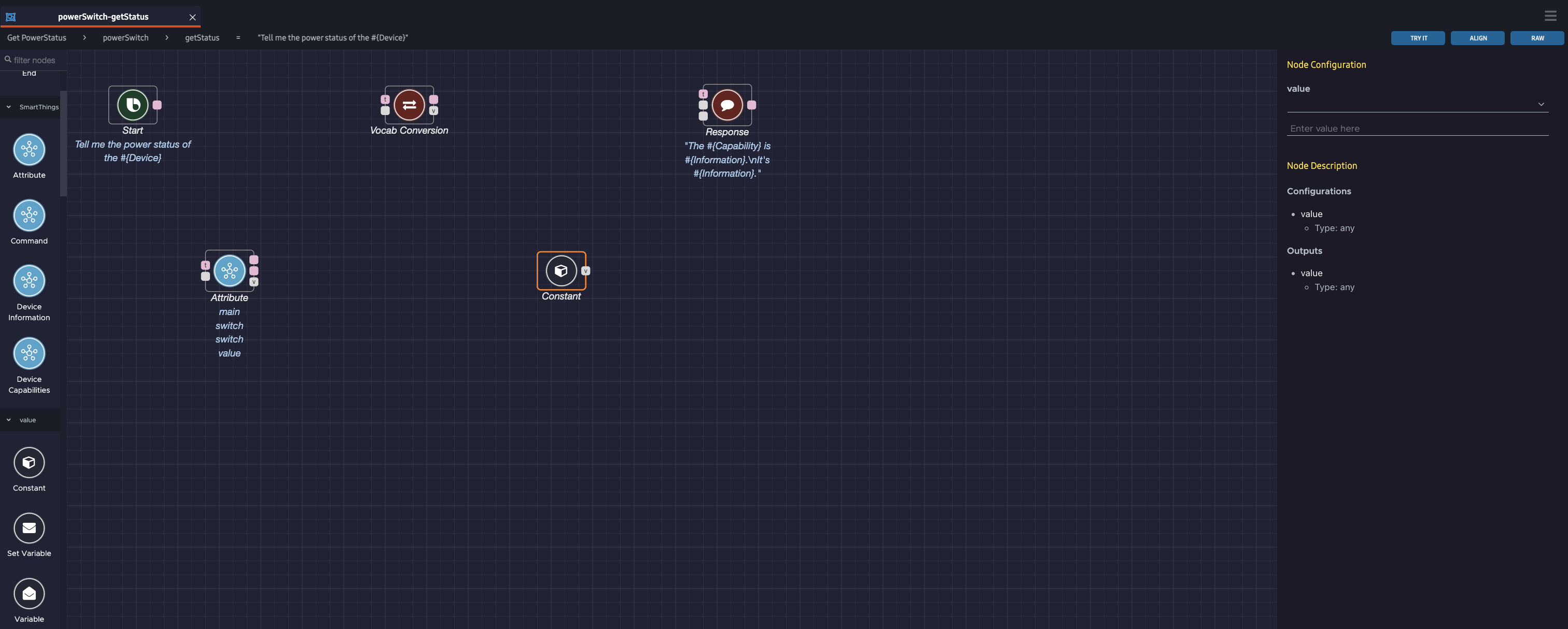
Select Vocab from the value menu at the top.
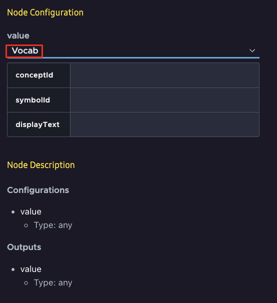
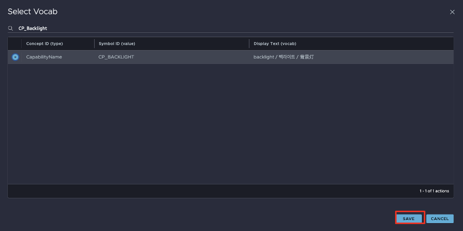
Click on the empty symbolId field. The Select Vocab pop up appears. For this example, select the "CP_BACKLIGHT" vocab and click SAVE.
The output port of the Constant node will be connected to the Capability parameter input port on the Response node.
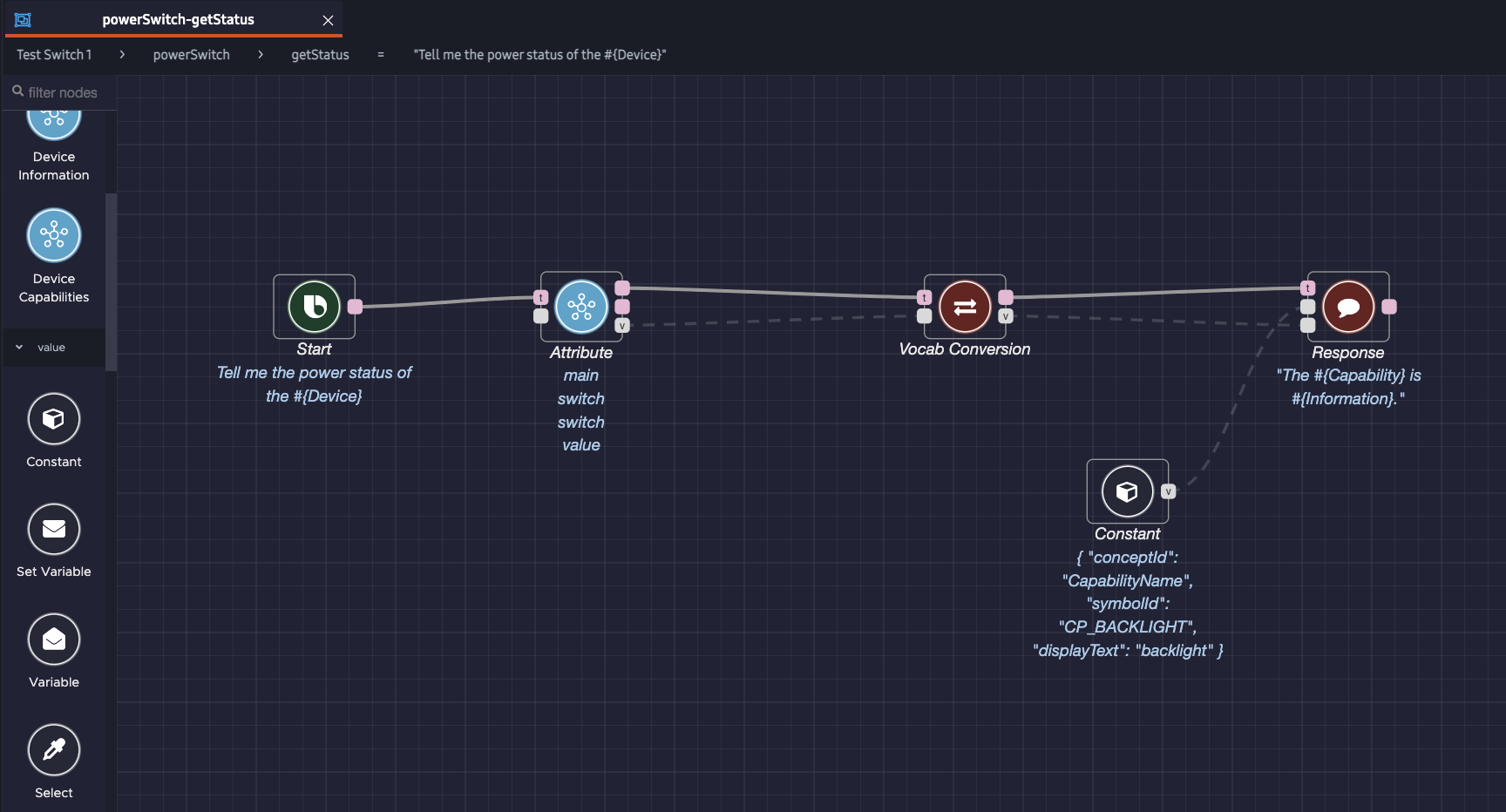
Add Execution and Data Paths
You have finished configuring the Constant node. Now, just connect the action flow nodes through execution and data paths.
Use a Trigger With the Attribute Node
Why not connect the Start node to the Attribute node's trigger port and have a linear execution path?
This produces the same outcome as that of the earlier graph. However, this graph behaves differently in terms of fetching the attribute value:
Attributenode in the execution path: Bixby fetches the value at runtime, when the node is triggered by other nodes. This potentially adds to the overall execution time of the action flow.Attributenode not in the execution path: Bixby fetches the value before the execution path is started. If the action flow needs several attribute values,Attributenodes not in the path will get the values in parallel. The execution time of the action flow does not increase with the number ofAttributenodes.
So, while the action flow above with the trigger in the execution path is valid, it's not as efficient as the first flow that prefetches the value of the attribute before the action flow is run. You should use triggers on Attribute nodes only when absolutely needed.
Test Your Action Flow
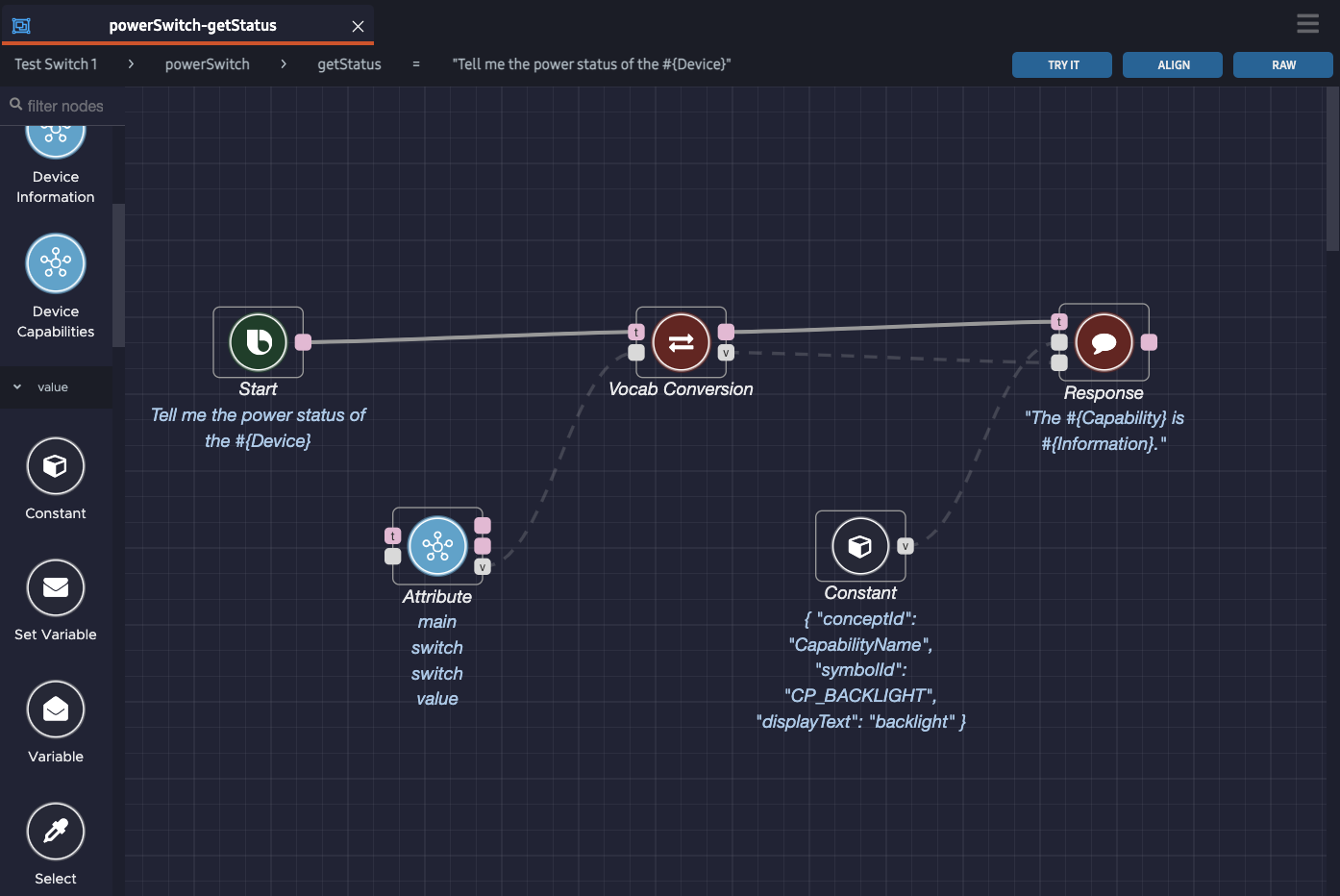
To test the action flow, click the Try It button at the top right of the editor window. The flow editor should look like this:
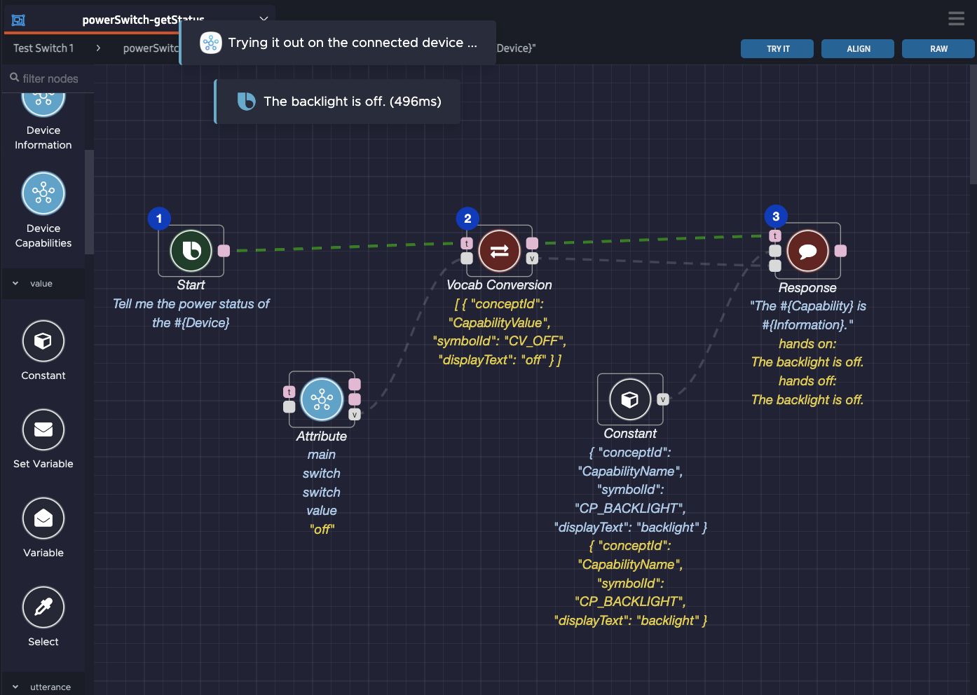
In this test run, Bixby responds to the user with "The backlight is off." Any obtained values or responses are shown below the corresponding nodes in yellow.
Additional Resources
The Node Recommendation feature enables you to get recommendations for next possible nodes, and can make it easier to create a graph.
For additional examples, see the "Tell Me the Fine Dust Level of the Device" Sample Graph and the "Set the Device Fan Mode to Auto" Sample Graph.
Video Tutorial: Attribute and Device Information
This video tutorial shows how to use device information and the Attribute node in your action flows.