
Creating Custom Device Labels
This guide assumes familiarity with the following information:
- The basics of the editor (Using Bixby Home Studio)
- The
Attributenode (Creating a Bixby Response Using Device Status) - The
Responsenode (Creating a Bixby Response Using Device Status)
In this guide, you'll learn how to use the Custom Label Feature to customize the device label names for user utterances. The device used in this guide is a SmartThings-enabled TV. You'll also learn how to use the following:
Example Custom Label Name: "Set the media input source of TV to PC."
In this example, "input source" is the device label name.
Start creating the action flow for this example by dragging a Start node and an Attribute node from the action flow nodes sidebar to the editor area. Then, connect the Start node's main port to the Attribute node's trigger port and configure the Attribute node to fetch the device's mediaInputSource.
Next, add a custom label to the Metadata.
Add a Custom Label to the Metadata
In the metadata sidebar on the left, click the add icon ![]() to the right of Labels in the Assets menu.
to the right of Labels in the Assets menu.
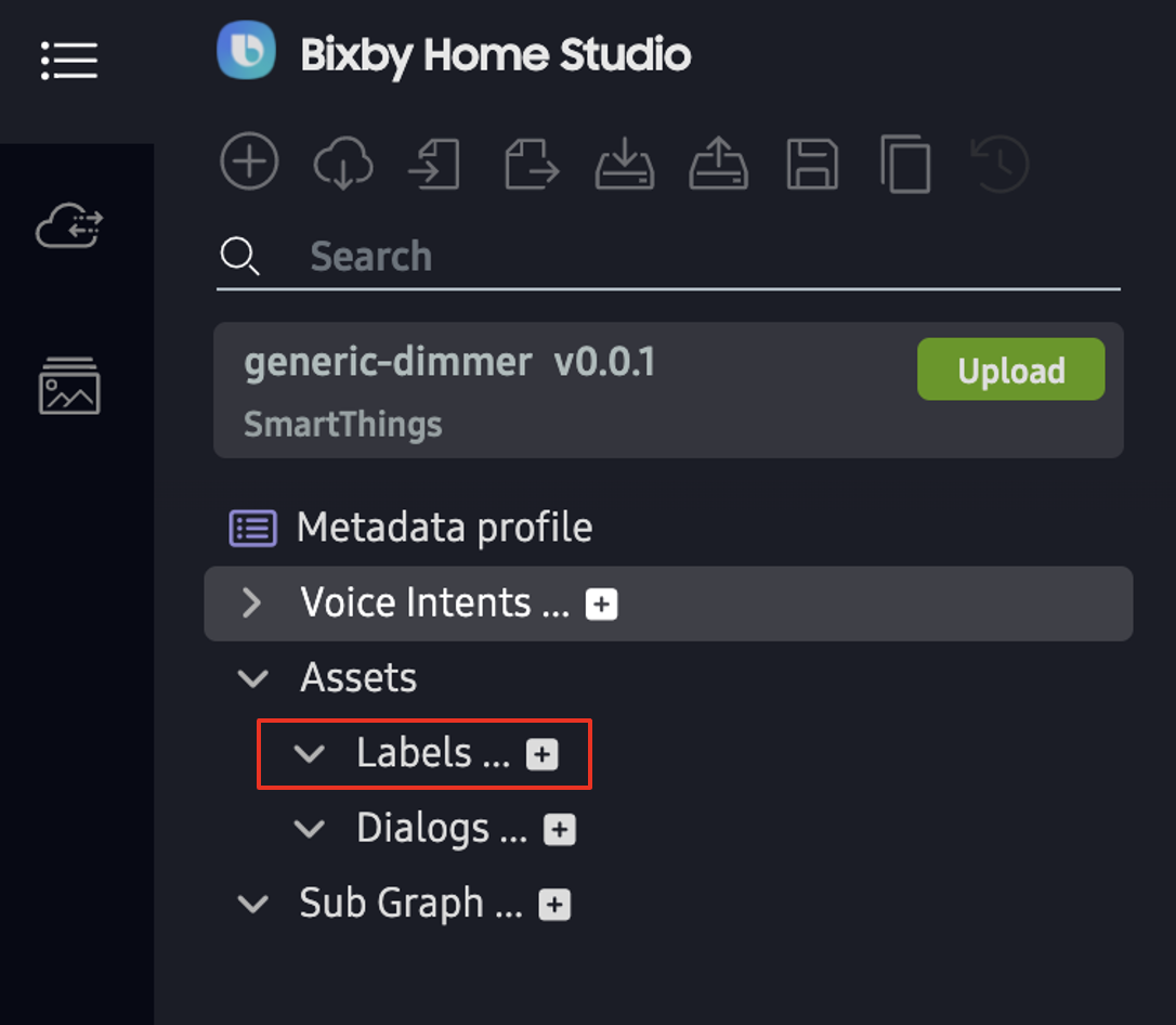
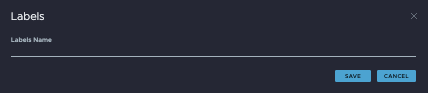
The Labels pop-up appears.
Next, create a custom label.
Create a Custom Label
- Type a custom label name for a device label and click SAVE. This example uses the device label name
inputSource.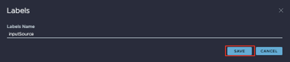 A tab opens and a Custom Labels table appears.
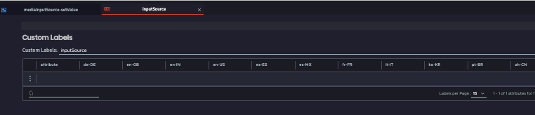
- Add a label attribute name to the attribute column and the relevant locale columns by double-clicking on a specific field. A label attribute is a device label attribute that can be recognized by the device. Label attributes are mapped to the custom label name, in this case
inputSource.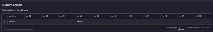
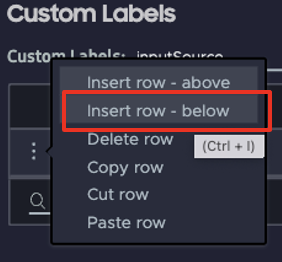
- Add more label attributes to the table as needed, by clicking the 3 vertical dots on the left and selecting Insert row - below.
Now, you can use the custom label in your action flow.
Use a Custom Label
To use a custom label in your action flow, do the following:
- Add one
toModeLabelnode to the graph. - Connect the success port of the
Attributenode to the trigger port of thetoModeLabelnode. - Add an
Utterance Localenode to the graph, which contains the locale of the user's utterance. - Configure the
Utterance Localenode to en-US by clicking on the node and selecting en-US from the menu.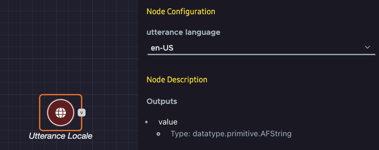
- Click the
toModeLabelnode. This opens the Node Configuration menu on the right.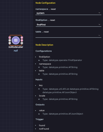
- Select metadata in the namespace menu and inputSource in the table menu. Leave the
findOptionas the default value offindFirst.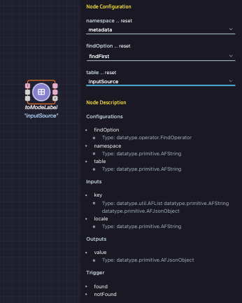
- Connect the
Attributenode's value port to thetoModeLabelnode's label port and theUtterance Localenode's value port to thetoModeLabelnode's locale port. - Add a
Constantnode and configure it to the string value "media input source."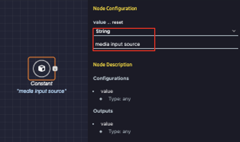
- Add a
Responsenode and configure it. This example uses the dialog template "The #{Capability} is #{Value}." Based on this template, the actual user dialog for this action flow would be "The media input source is PC." - Connect the
toModeLabelnode's found port to theResponsenode's trigger port, and its value port to theResponsenode's value port. - Connect the
Constantnode's value port to theResponsenode's capability port.
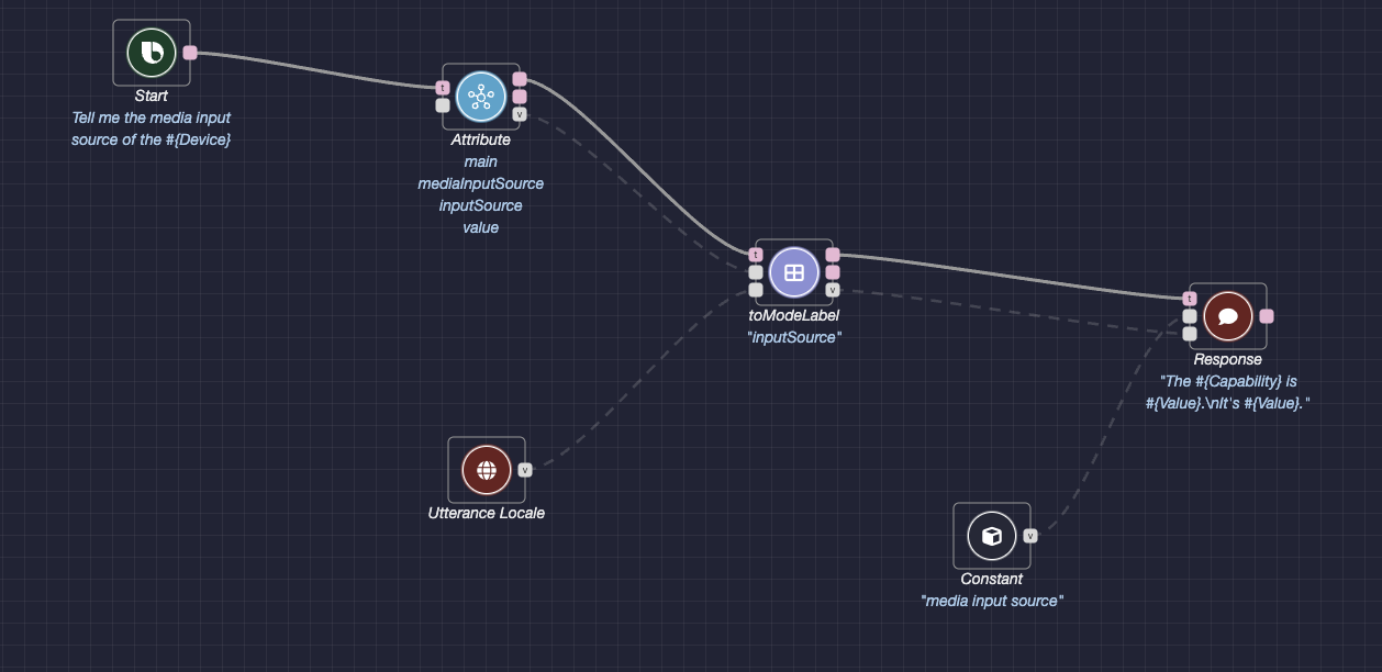
This is the final action flow:
You can test your action flow in BHS with the TRY IT feature.
Test Your Action Flow
To test the action flow, click the Try It button at the top right of the editor window. The flow editor should look like this:
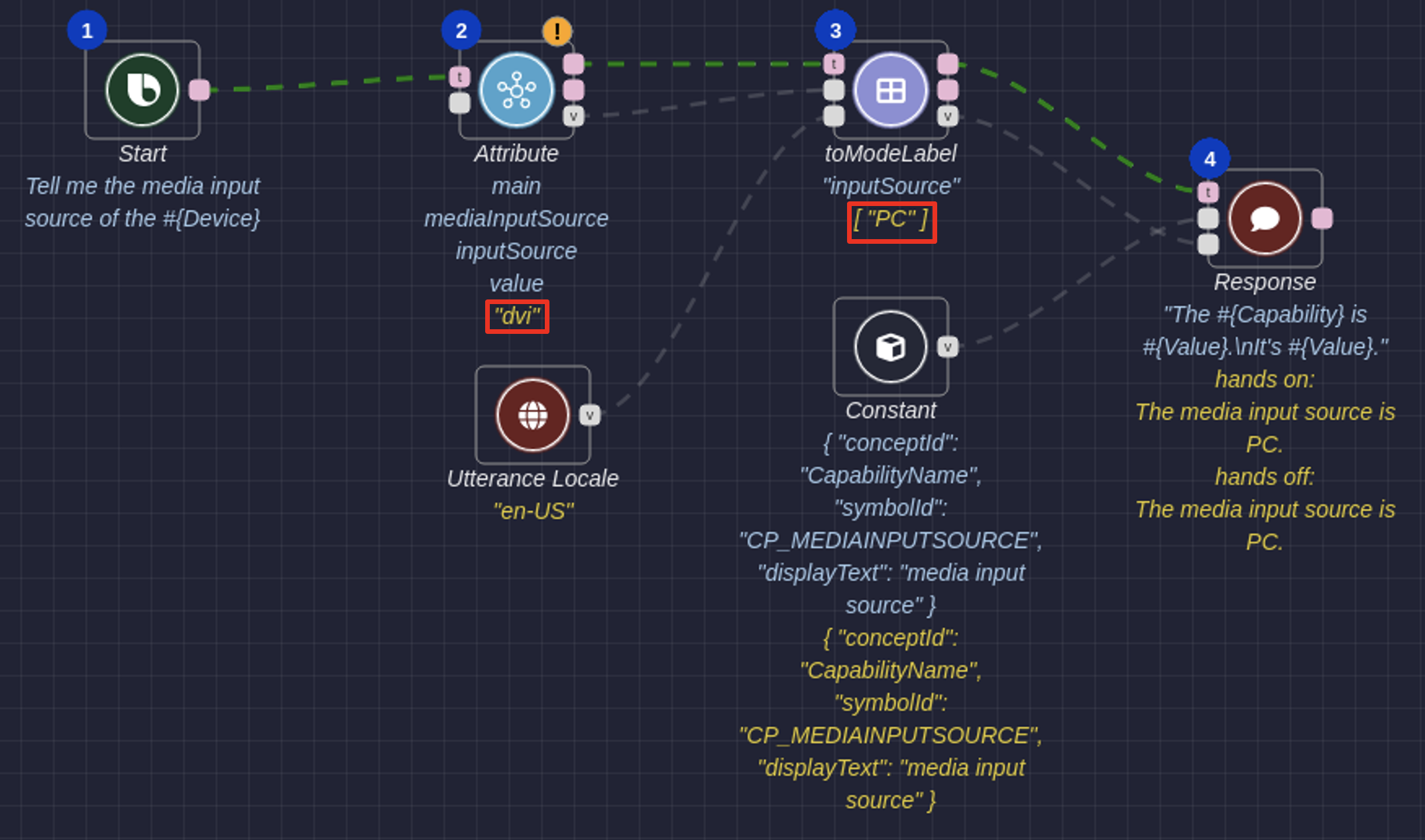
In this test run, Bixby first fetches the device's current inputSource, which is "dvi." Then, Bixby sets the device's inputSource to "PC" in the en-US locale. Finally, Bixby responds to the user by saying "The media input source is PC."
Additional Resources
The Node Recommendation feature enables you to get recommendations for next possible nodes, and can make it easier to create a graph.
Video Tutorial: Custom Responses and Prompts
The following video tutorial gives another example of how to use custom responses and confirmations in BHS.